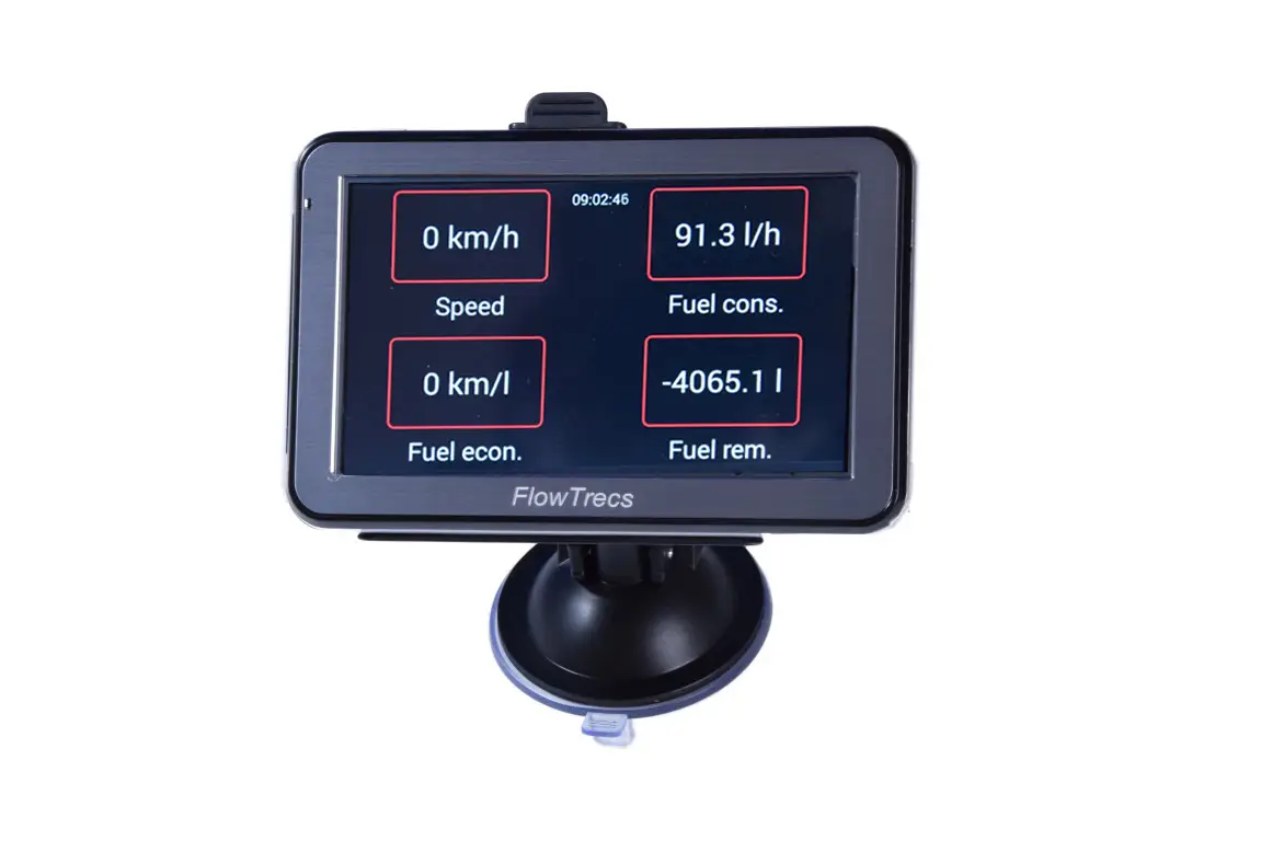
1. Define the symptom: a fluctuating display or an inflated total?
These are different problems. The instantaneous reading may fluctuate while the accumulated consumption remains correct. If the total rises faster than the actual fuel used, do not try to hide it with longer averaging.
Record feed flow, return flow, net result and the increase in accumulated consumption separately. Note engine speed, load, steady-test duration and whether the system was cold, warming up or at normal operating temperature. Also record whether the reading is high at idle, becomes more plausible as speed rises or crosses below zero.
2. Why is differential measurement sensitive to pulsation?
In a typical return-line diesel, one sensor measures all fuel sent to the engine and a second measures fuel returning to the tank. The computer calculates:
net consumption = feed flow − return flow
Both flows can be much larger than net consumption. In the example 60 l/h − 52 l/h = 8 l/h, changing one channel by only 1 l/h changes the net result by 12.5%. This is a mathematical illustration, not an FS-40 accuracy specification. It shows why relative net error grows at low load.
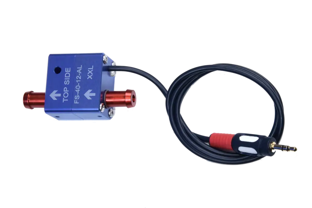
The FS-40 is a turbine sensor: rotor movement generates pulses, while the pulse signal does not identify the direction of movement. Pulsation or momentary reverse flow can move the rotor again and produce additional pulses that are counted as flow. This inflates the affected channel reading. Extra pulses on the feed can inflate net and accumulated consumption, while extra pulses on the return can reduce them or cause momentary negative values; if both lines pulsate, the effect depends on the imbalance between them. Air bubbles can further disturb both measurement channels.
- Small display movement with an accurate total can follow normal load changes or governor behaviour.
- Pulsation with momentary reversal can add pulses and alter accumulated consumption as well.
- Air or foam changes the conditions of volumetric measurement; the source of air ingress or foaming must be removed.
One return-line diesel needs two sensors; two such engines need four sensors, arranged as two independent feed-and-return pairs. The guide to diesel measurement and sensor selection explains the principle in detail.
3. Check channel configuration and each sensor range
- Confirm diesel mode and the correct number of active sensors.
- Identify feed and return channels; on a twin-engine system, check both pairs separately.
- Compare the exact FS-40 sensor variant on each line with the device configuration.
- Verify that minimum and maximum range cover the full flow present in that particular line.
If pump capacity is unknown, do not infer it from engine power or an idle reading. Record the exact engine and pump models, then confirm sizing from manufacturer data or with Flowtrecs.
4. Exclude installation errors, vibration, leaks and air
- The arrow on each sensor must follow the actual flow direction in its line.
- Mount the sensor horizontally with TOP SIDE uppermost, without hose strain or excessive vibration.
- All fuel counted on the feed side but not burned must return through the return sensor — check injector leak-off, regulator, cooler, bypasses and tank valves.
- Position relative to the pump and filter must follow current Flowtrecs and engine instructions and any installation-specific requirements.
- Connections must be leak-free, the filter clear, sensors filled with fuel and hoses free of kinks or points that can draw air.
- Fill and bleed the system completely using the engine manufacturer's procedure.
Do not improvise with transparent hose, an air pocket or a reversed filter. Do not copy filtration ratings, hose lengths or sensor positions from another manufacturer's instructions either — different technologies have conflicting requirements. If air must be observed directly, a competent service technician should use an approved, safe method. The full checklist is in the guide to installing an FS-40 sensor.
5. Compare channels at several steady loads
Do not judge the installation only at idle. Under safe conditions permitted by the manufacturer and with a responsible operator in control, run short repeatable checks at several steady engine speeds and loads. Record feed, return, net and total increase at every point.
| Observation | First checks |
|---|---|
| Only one channel is unstable | That line, air, vibration, sensor, cable and input channel |
| Net is too high at idle but more plausible under load | Pulsation or reverse flow, the lower end of the sensor's operating range and pump behaviour; do not calibrate from idle |
| Net occasionally becomes negative | Channel assignment, sensor arrows, asymmetric pulsation between the two lines and the effect of warm return fuel |
| The result changes mainly during warm-up although both channels are stable | Feed/return temperature difference and whether the measurement boundary includes every return branch; Flowtrecs does not compensate for temperature |
| Both channels look plausible but net remains consistently wrong | Ranges, factory calibration, error amplification caused by subtraction, an unmeasured branch and a longer total-consumption check |
| Display fluctuates but the total remains accurate | Only after faults are excluded, consider the averaging setting documented for that model |
| Total rises too fast although the display is smoother | Air, reverse flow, pump pulsation, range and configuration; averaging does not remove the cause |
If the device exposes individual channels, retain photos or a short video showing both readings at the same time. The net value alone contains less diagnostic information.
6. Locate the source without opening the fuel system unnecessarily
First check labels, cable condition and visible connectors without opening the fuel system. Check electrical connections with the engine and device power off, following the exact model's instructions.
If the cause remains unclear, send Flowtrecs a record of both channel readings and installation photos. The behaviour of the readings after reconnecting cables alone does not establish whether the cause is a sensor, wiring, an instrument input or fuel flow in the line.
Leave input comparisons and any sensor swapping to a competent service technician, after Flowtrecs has confirmed compatible variants and a safe procedure. Do not swap channels or sensors by trial and error.
7. Check valve, pulsation damper and averaging: when do they help?
Flowtrecs instructions note that the condition and behaviour of a feed pump or injectors can make an additional check valve or pulsation control necessary in some installations. This does not mean that every diesel needs one.
Other manufacturers use different solutions: sensors that detect momentary reverse flow, matched flowmeter pairs, temperature measurement or dedicated dampers. The required mounting position, filtration and hose geometry are specific to each technology and cannot be transferred directly to the FS-40.
Averaging is model-specific. It can steady a valid but pulsating displayed value, but it cannot cancel extra pulses or correct air ingress, an incorrect range or an inflated accumulated total. If the total is wrong, return to hydraulic diagnosis instead of increasing averaging or calibration correction.
8. Calibrate only after removing the cause and prepare service data
Sensors are factory-calibrated. Any user correction is model-specific and is not available on every device. Consider it only after the system is leak-free, fully bled and producing repeatable readings, and after a total-consumption check confirms the discrepancy. Calibration performed with pulsation, air or a changing temperature effect may improve one operating point and worsen others.
For a total check, fill to a repeatable level, reset the trip total, use a meaningful quantity of fuel in normal operation, then refill the same tank with similar trim to the same level. Fuel transfer, other consumers or a different fill level invalidates the comparison. Do not run an open-container test or disconnect the return line.
Include the following with a service request:
- device model, software version and exact sensor variants;
- engine, injection-system and pump models plus a complete feed, leak-off and return diagram;
- minimum and maximum operating flow and pressure limits for both lines;
- feed, return, net and total readings at several steady speeds under safe load, including warm-up state;
- actual fuel used and how it was measured;
- photos of sensor direction, orientation and connections, plus a video of the symptom;
- checks already performed; if a service technician carried out agreed swap tests, include their description of the results and observations.
The general reading checks and cautious correction rules are covered by Flowtrecs calibration and troubleshooting.