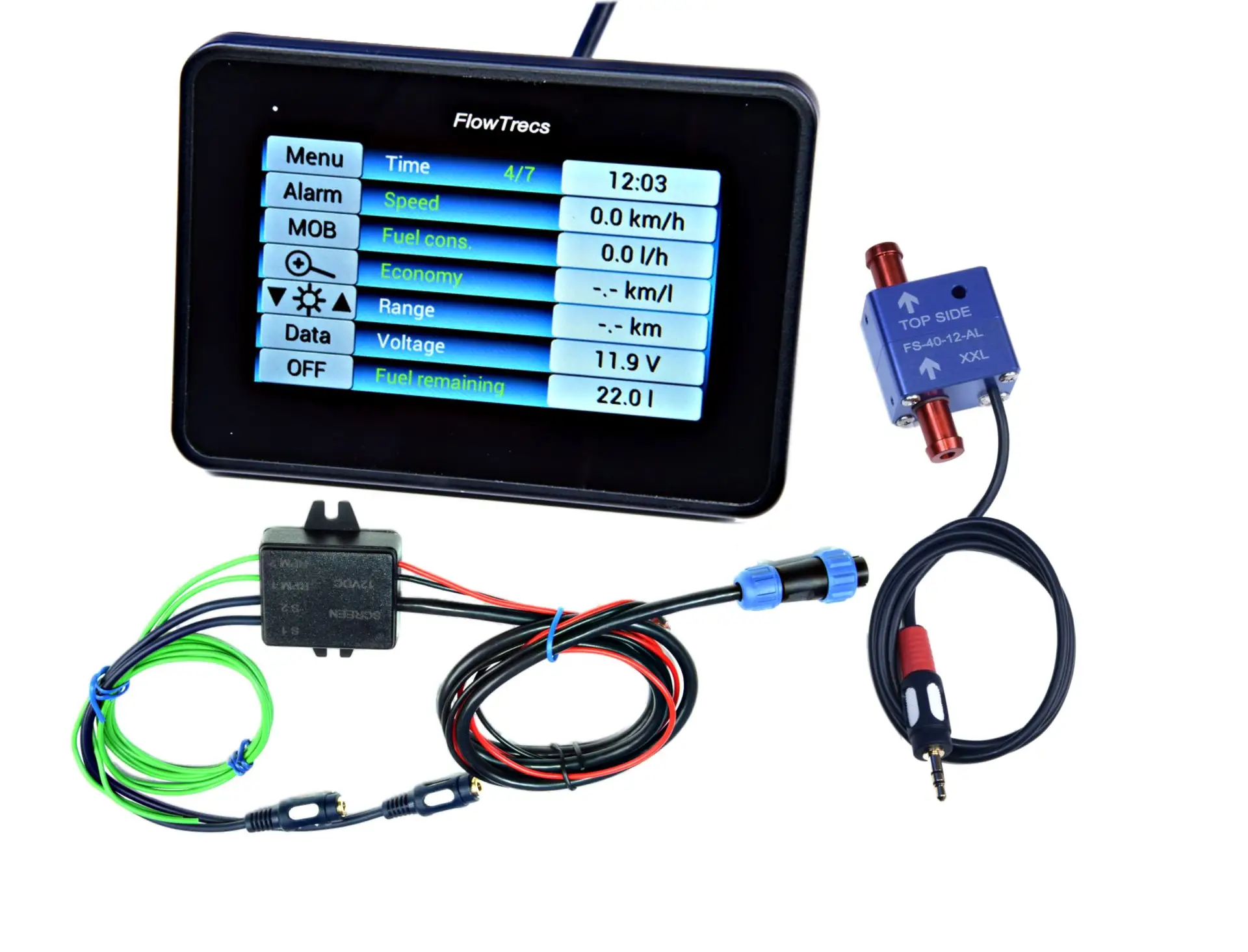
1. Start with the real fuel-system layout
The installation, not the engine label alone, determines sensor count. First confirm whether unused fuel really returns to the tank through a separate line.
In a typical return-line diesel, the pump delivers more fuel to the engine than is burned at that moment. The excess returns to the tank, so feed-line flow alone is not yet fuel consumption.
Trace the lines using the engine and installation documentation. The measurement boundary must be closed: all fuel counted by the feed sensor but not burned by the engine should return through the return sensor. This includes return flow from injector leak-off lines, the pressure regulator, a fuel cooler and any other return branches.
- Check whether return fuel goes directly to the tank, a filter, a local loop or a day tank.
- Include injector leak-off, bypasses, tank selector valves and cross-connections between tanks.
- Confirm every valve operating state, not only its position during inspection.
2. Differential measurement: feed minus return
Two sensors measure the full feed stream and the return stream at the same time. A compatible Flowtrecs computer calculates net consumption:
net consumption = feed flow − return flow
A purely illustrative example: 60 l/h feed − 52 l/h return = 8 l/h net consumption. These figures are not sensor-range guidance.
Subtraction magnifies even a small difference between channels. In the example above, changing only one reading by 1 l/h changes net consumption from 8 to 7 or 9 l/h — a 12.5% change. This is a mathematical illustration, not an FS-40 accuracy claim; it shows why low-load differential measurement is more demanding.
The computer derives current consumption from the channel difference, while flow accumulated over time produces total consumption. The guide to how Flowtrecs measures fuel consumption explains the general principle.
3. How many sensors and which Flowtrecs computer?
| Confirmed layout | Sensor count | Suitable families |
|---|---|---|
| 1 diesel with a return to the tank | 2: feed + return | Wave, Android BT, C7 Ultra or App in a 2-sensor variant |
| 2 diesels, each with its own return | 4: two pairs | Wave, Android BT, C7 Ultra or App in a 4-sensor variant |
Flowtrecs Inox and Flowtrecs Mini support a maximum of one sensor, so they cannot perform differential measurement for a typical return-line diesel. Appropriate variants of Wave, Android BT, C7 Ultra and App support two or four lines.
4. Check each line's lower and upper flow limits
Size each sensor for the minimum and maximum actual flow in its own line. Actual pump delivery in the installed system matters on the feed side; actual return-line flow matters on the return side. A pump's free-flow catalogue figure is useful input, but it is not always the installed operating flow.
Every Flowtrecs FS-40 sensor has lower and upper operating limits. An undersized variant may be overloaded and add unacceptable restriction, while an oversized variant may operate below its reliable range at idle or trolling speed. Do not size either sensor from net fuel burn, the calculation example or engine power alone.
- minimum and maximum operating flow separately in feed and return;
- exact engine, injection-system and fuel-pump make and model;
- permitted feed-side vacuum or restriction and return-line backpressure;
- fuel-hose internal diameter, filter, valves and connection details;
- Flowtrecs confirmation of whether this kit requires the same FS-40 variant on both channels.
If the data is incomplete, send the engine and pump models plus a line diagram to the Flowtrecs team for a selection check.
For worked examples, limits of the 2.5–3 × fuel-burn estimate and FloScan comparisons, see how to choose the FS-40 sensor range.
5. Good installation creates the right measuring conditions
With differential measurement, both streams should be measured under comparable and stable conditions. For each sensor:
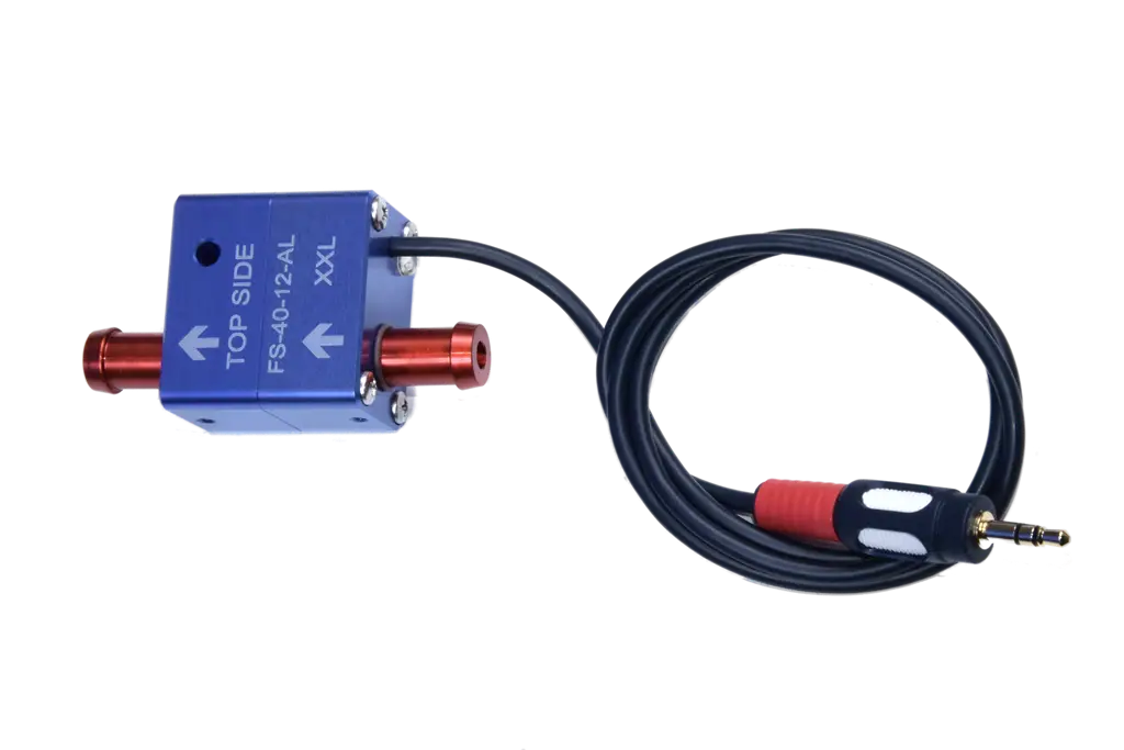
- point the arrow in the actual direction of flow;
- mount it horizontally with TOP SIDE uppermost;
- protect it from excessive vibration, heat and hose strain;
- make leak-free, fuel-compatible connections and keep the sensor chamber filled with fuel;
- fill and bleed the system in accordance with the engine manufacturer's instructions;
- perform the required leak test and verify that operating pressures remain within the specified limits.
Filtration, straight-run requirements and position relative to a pump are specific to the sensor and engine. Do not copy micron ratings, hose lengths or mounting positions from another flowmeter manufacturer's instructions. Use the current Flowtrecs instructions for the FS-40 together with the engine manufacturer's limits. The guide to installing an FS-40 sensor provides a detailed checklist.
6. How should you assess the result after commissioning?
The sensors are factory calibrated, so commissioning starts with observation rather than a coefficient change. Check several steady engine speeds and loads after warm-up and, where practical, while the fuel system moves from cold to normal operating temperature.
In a typical return-line diesel, net consumption is a small difference between two larger flows. At idle that difference can be particularly small, so natural movement in the current value and the effect of both channel errors become more visible.
Compare total consumption only after using a meaningful quantity of fuel. Fill to a repeatable level, reset the trip total, operate normally, then refill the same tank with similar trim and to the same level. Fuel transfer between tanks, other fuel consumers or an inconsistent fill level invalidates the comparison. A tank-level gauge is not itself a volume reference. Do not run an open-container test or disconnect the return line.
7. Pulsation can occur and can usually be identified
Some fuel pumps produce pulsating flow. This is a characteristic of a particular hydraulic system, not a fault in every diesel and not automatically a measurement problem. Small movements in the current value can be a normal response to pump operation and changing load.
If the indication is clearly unstable, the accumulated total does not agree with actual fuel use, or the behaviour repeats within a particular operating range, use a structured diagnostic procedure. See diesel fuel-flow pulsation troubleshooting.
8. Connecting the RPM signal
Diesel: an additional Hall sensor may be required if the engine does not provide a suitable electronic RPM signal.
9. Prepare the details and selection becomes straightforward
For an enquiry or order, prepare: engine, injection-system and pump models; a complete diagram showing the feed line and every return branch; minimum and maximum flow in each line; pressure limits; hose diameter; and the preferred display type.
- Confirm where the main return, injector leak-off and every additional branch lead.
- Record operating feed and return flows or provide exact component designations.
- Add permitted feed vacuum and return backpressure from the engine documentation.
- State whether the installation has one or two engines and needs a 2- or 4-sensor kit.
- Add photos of lines, filters, valves and the proposed mounting area.
- Select Wave, Android BT, C7 Ultra or App according to display and mounting needs.
Review the FS-40 sensor, compare Flowtrecs devices or send the installation details for verification.