Before cutting a fuel hose
First confirm the number of measuring points, the required flow range and the exact FS-40 sensor version. One line needs one sensor; a return-line system needs separate feed and return measurements. See how many sensors your installation needs.
- Switch off the ignition and nearby electrical equipment.
- Shut off the fuel supply as specified for the boat and engine.
- Provide ventilation, a suitable extinguisher and fuel-approved materials.
- Prepare matching sensors, hoses, fittings and clamps.
Horizontal, TOP SIDE upwards and arrow with the flow
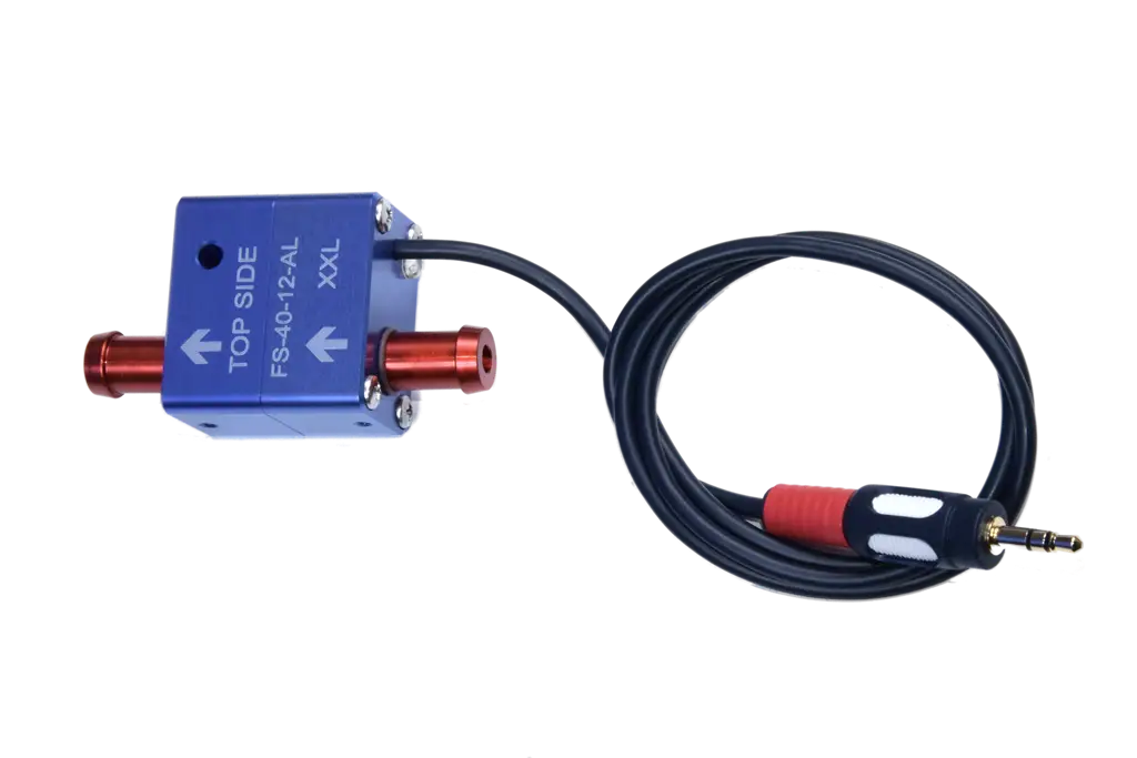
Install the FS-40 horizontally with the face marked “TOP SIDE” upwards. The arrow on the body must point in the actual direction of fuel flow.
Select a position above tank level, accessible for inspection and as far as practicable from strong vibration and heat. The sensor must not carry the weight of the fuel hoses or act as a structural support.
Support the hoses so that the sensor fittings are not twisted or side-loaded. Leave enough access to inspect the markings and connections and to service the system without dismantling unrelated equipment.
Where should the sensor sit in the fuel system?
The sensor measures only the line in which it is installed. Flowtrecs manuals show the fuel filter before the sensor; the Wave and Android BT instructions place the sensor between the filter and engine. The complete system must still follow the engine manufacturer's requirements for filtration, pumps, bleeding and permissible flow restriction.
Match the small tail to 8 mm ID hose or the large tail to 10 mm ID hose
S and M: hose with an 8 mm internal diameter. L, XL, XXL and 3XL: hose with a 10 mm internal diameter. The 9.5 mm measurement on the small tail and 11.1 mm on the large tail are diameters at the raised sections of the tails, not hose internal diameters.
- Check the internal diameter of the hose and match it to the sensor version.
- Use hose, fittings and clamps approved for the fuel concerned.
- Do not force a mismatched hose onto a fitting or create arbitrary restrictions.
- Route the hose without kinks, abrasion or strain at the tails.
The joint should seal mechanically without excessive clamping that could damage the hose or fitting.
Power supply and electrical routing
Flowtrecs equipment is nominally intended for a 12 V installation. Direct connection to 24 V is prohibited and can damage the electronics. If the boat uses 24 V, agree the correct solution with Flowtrecs or a competent installer before connection.
- Disconnect power while making connections.
- Use the protection and connection method specified in the device manual.
- Protect connectors from water, fuel, abrasion and pull-out.
- Keep wiring away from hot parts and strong interference sources.
The sensor plug is not a waterproof connection. Seal it as specified for the kit, for example with the tape or heat-shrink method stated in its instructions.
Bleeding and the first start
After installation, restore the fuel supply and prime and bleed the system using the engine manufacturer's procedure. The Inox and Mini instructions specify using the primer bulb. With correct flow, the sensor's internal green LED is active: it flashes at low flow and may look continuously lit at higher flow. Air can cause a missing reading, fluctuating values and engine-running problems.
- Recheck the arrow, TOP SIDE position and hose support.
- Bleed the system before judging the reading.
- Inspect every connection before starting.
- Start the engine safely and inspect for leaks again.
- Observe the reading first at idle and then as load changes.
If fuel can be smelled or seen at a joint, or the engine runs abnormally, stop it and correct the cause before leaving the berth.
Connecting the RPM signal
Reading RPM from the ignition signal of a carbureted petrol engine requires an additional Tacho Pulse Limiter. Two versions are available: IN — for inboard engines and OUT — for outboard engines.
For fuel-injected engines (EFI/DFI), a limiter is typically not needed when using a suitable electronic tachometer output.
The limiter is used only for RPM readings and is not required to measure fuel consumption.
Diesel: an additional Hall sensor may be required if the engine does not provide a suitable electronic RPM signal.
Pre-departure checklist
- The sensor is horizontal, TOP SIDE upwards and above tank level.
- The arrow follows the actual direction of flow.
- S and M: hose with an 8 mm internal diameter. L, XL, XXL and 3XL: hose with a 10 mm internal diameter.
- Connections are leak-free and hoses do not load the sensor.
- The system is bled and the reading responds as load changes.
- The supply meets the 12 V requirement and no direct 24 V is applied.
If the reading remains at zero or fluctuates after a correct installation, use the Flowtrecs calibration and troubleshooting guide. You can also compare the product range or send the installation details for review.