What does the FS-40 measure?
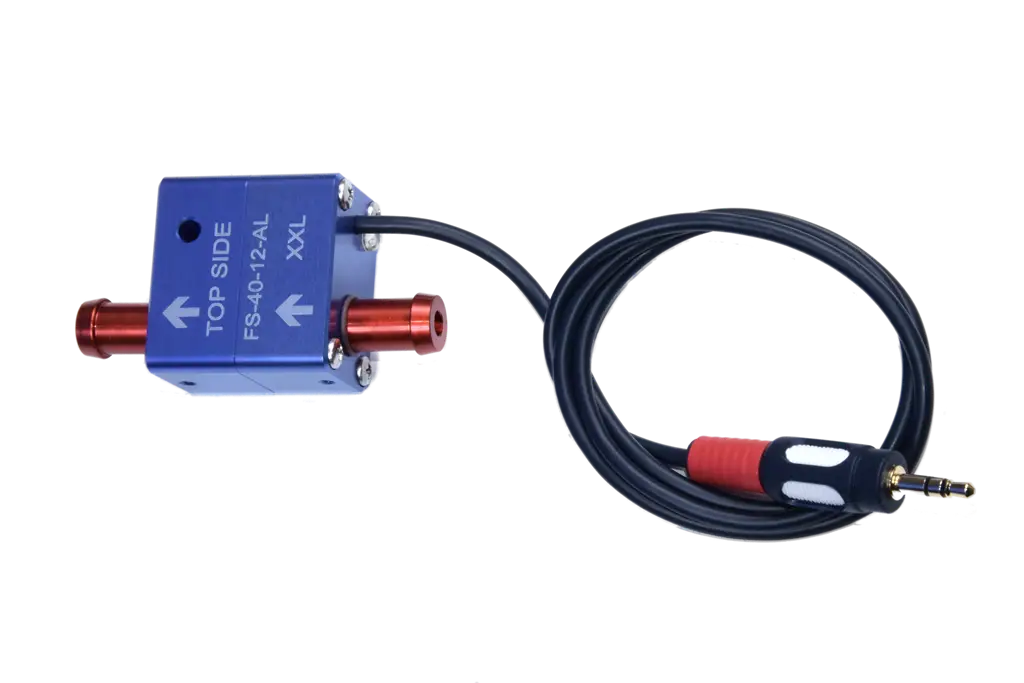
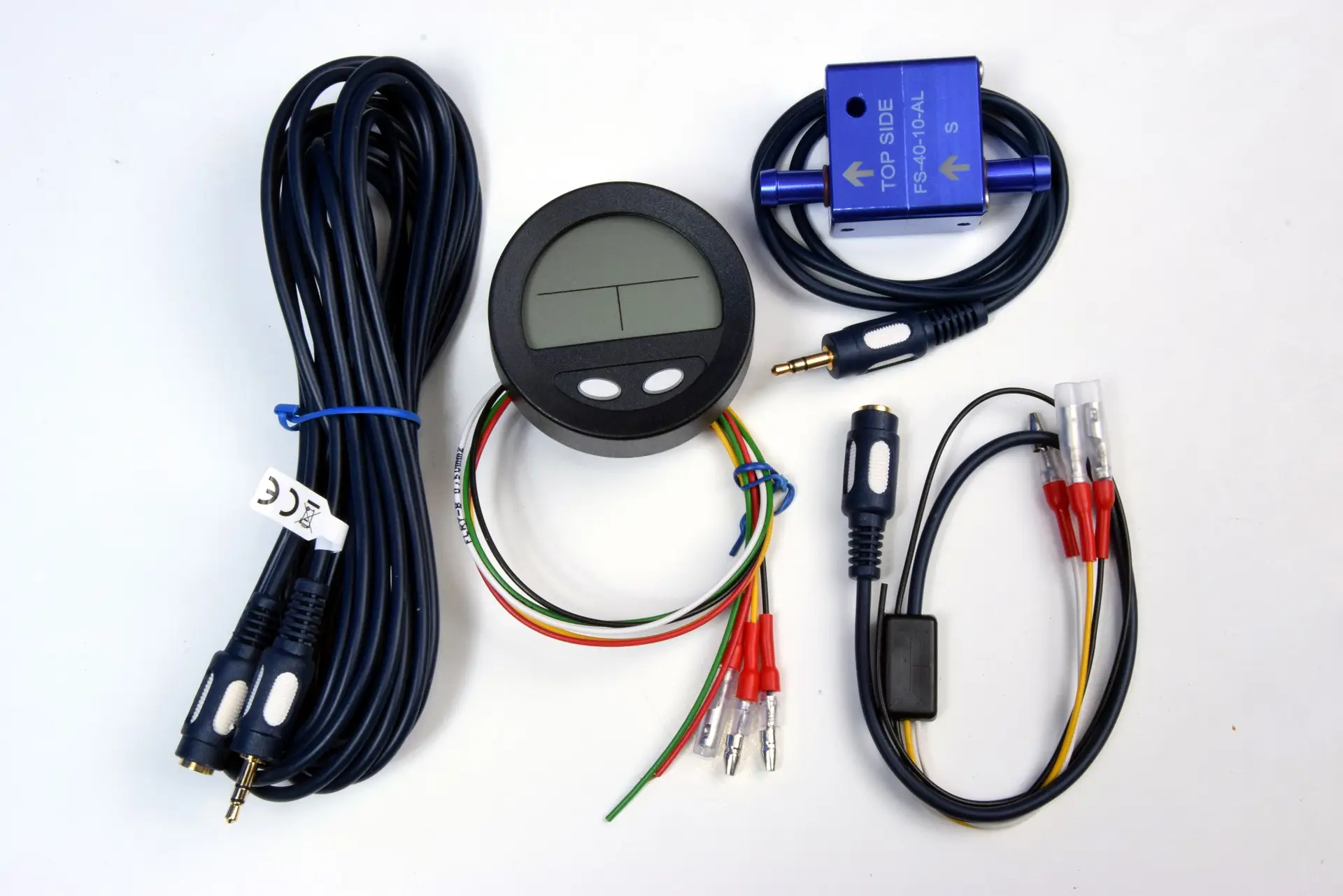
The FS-40 is a turbine flow sensor installed in a fuel line. Fuel flow turns its internal rotor, and the Flowtrecs computer uses the sensor output to determine litres per hour and accumulated fuel consumption.
One sensor measures one fuel stream. It cannot decide on its own whether some of that fuel later returns to the tank. The line layout therefore determines whether one reading is enough or whether two readings must be compared.
The FS-40 is available in several flow ranges. The selected range should cover operation at low load as well as the maximum flow that can occur in that line.
Measurement without a return line
If fuel travels from the tank through the sensor to the engine and does not return through a separate line, feed flow corresponds to the amount delivered to that engine. One sensor serves one independent fuel circuit.
This layout is common on many petrol engines. A single-channel computer such as Inox or Mini is sufficient for one petrol engine without a return line. Two petrol engines without return lines use two sensors and a device supporting two channels.
Differential measurement: feed minus return
In a return-line system, the first sensor measures all fuel sent towards the engine and the second measures fuel going back to the tank. A computer that supports differential measurement calculates:
net consumption = feed flow − return flow
A purely mathematical example: 80 l/h in the feed and 60 l/h in the return equals 20 l/h net consumption. These figures are not sensor-sizing guidance.
One return-line diesel therefore requires two sensors; two such engines require four. The device variant must support the correct channel count and differential operation.
What changes with a second engine?
Each engine has its own fuel circuit, so its measuring points must be duplicated. A multi-channel computer can show separate engine figures and a combined total, but it cannot replace a missing sensor in any line.
| Installation | Measurements | Total sensors |
|---|---|---|
| 2 engines without return | Engine 1 feed + engine 2 feed | 2 |
| 1 engine with return | Feed + return | 2 |
| 2 engines with return | Two feed-and-return pairs | 4 |
See the complete product-and-variant matrix in how many sensors an installation needs.
Sensor selection: petrol versus diesel
For a typical petrol engine without a fuel return line, the engine-power bands shown in the shop are a practical starting point for sensor selection. Confirm the engine model and maximum fuel consumption. For a diesel with a return line, size each sensor for the minimum and maximum actual flow in its own line — supply and return separately — not engine power or net fuel burn alone.
The most useful figures are the minimum and maximum actual operating flow in each line. Maximum pump delivery is a useful starting point, but it does not replace data from the real circuit.
How does km/l help reduce fuel use?
A litres-per-hour reading tells you how much fuel the engine is using at that moment, but it does not show how far the boat travels on that fuel. By combining actual consumption with speed, the computer can calculate fuel economy:
fuel economy [km/l] = speed [km/h] ÷ consumption [l/h]
Illustrative example: 32 km/h ÷ 16 l/h = 2 km/l. In unchanged conditions, each litre then corresponds to two kilometres of travel.
Fuel use changes non-linearly with speed and load. Trim, weight distribution, hull condition, water conditions and propeller choice also matter. RPM alone therefore cannot reliably show whether a small adjustment will increase or reduce range.
During a safe passage, hold conditions steady for a moment and change only one parameter, such as engine speed or trim. Comparing km/l before and after the change helps identify the operating point that delivers the greatest distance from one litre.
Direct measurement and calculated values
Fuel flow is the system's direct measurement. Depending on the model, the computer can use it to show current and total consumption. Combined with speed, it can also present fuel economy in km/l.
Remaining fuel and estimated range are calculated from settings and recorded consumption; they are not the same as a direct liquid-level measurement in the tank. RPM, voltage and engine hours use the relevant inputs or device data.
Fuel economy is available in the Inox, Mini, Wave, standard Android BT, C7 Ultra and App families. They differ in display, speed source, mounting, water protection and supported sensor count. The Flowtrecs model comparison sets out those differences.
Connecting the RPM signal
Reading RPM from the ignition signal of a carbureted petrol engine requires an additional Tacho Pulse Limiter. Two versions are available: IN — for inboard engines and OUT — for outboard engines.
For fuel-injected engines (EFI/DFI), a limiter is typically not needed when using a suitable electronic tachometer output.
The limiter is used only for RPM readings and is not required to measure fuel consumption.
Diesel: an additional Hall sensor may be required if the engine does not provide a suitable electronic RPM signal.
What should you check if a reading looks wrong?
Check the system first: return-line coverage, sensor count, each FS-40 range, installation direction, bleeding and channel configuration.
When planning a diesel installation, start with the guide to differential measurement and sensor selection. For the full zero, unstable or consistently incorrect reading procedure — including averaging and safe calibration assessment — use the Flowtrecs calibration and troubleshooting guide.
Also review the FS-40 specification or ask about your installation.